ENGINEERING DRAWING (Code No. 046)
The subject of 'Engineering Drawing' has become an indispensable tool for Engineers, Technocrats, Architects, Draftsmen, Surveyors, Designers and many others professionals in the recent times. Understanding of its fundamental principles and wider applications of the same in the above fields and many other daily life situations form the basis for the syllabus at Senior Secondary Stage.
Objectives:
The study of the subject of Engineering Drawing at Senior School Level aims at helping the learner to:
• develop clear concept and perception of form, proportion and purpose.
• develop the skill of expressing three-dimensional and two-dimensional objects into professional language and vice versa.
• acquire the ability to readily draw neat sketches, often needed in "On-job situations".
• develop a clear understanding of plane and solid Geometry and machine drawing so as to apply the same in relevant practical fields such as technology and industry.
• acquire speed and accuracy in use of drawing instruments.
COURSE STRUCTURE
Class XI (Theory)
-----------------------------------------------------------------------------------------------------------------------------------------------------
One Paper 3 Hours 70 Marks
-----------------------------------------------------------------------------------------------------------------------------------------------------
Unit Marks
PLANE GEOMETRY
1. Construction of lines, angles and rectilnear figures 4
2. Construction of circles, semi-circles and tangents 6
3. Construction of ellipse, parabola, involute, cycloid. helix and sine-curve 6
SOLID-GEOMETRY
4. Orthographic-projections of points, lines laminae, (plane) and solids 12
5. Section of solid-figures 15
MACHINE DRAWING
6. Orthographic projections of simple machine-blocks 12
7. Isometric-projection of laminae (plane) figures 10
8. Development of surfaces 5
-----------------------------------------------------------------------------------------------------------------------------------------------------
Total Marks 70
-----------------------------------------------------------------------------------------------------------------------------------------------------
PLANE GEOMETRY
Unit 1: Construction of lines, angles and their divisions. Simple questions based on triangles, squares, rhombuses, trapeziums, regular polygons-pentagon, hexagon and octagon. 08 Pds.
Unit 2: Construction of circles, external and internal tangents of circles, inscribing of circles in equilateral triangle, square, rhombus, regular polygons-pentagon, hexagon and octagon. 10Pds.
Unit 3: (a) Construction of ellipses by the following methods:
(i) Concentric circles
(ii) Intersecting arcs
(iii) Intersecting lines
(b) Construction of Parabola by the following methods:
(i) Intersecting lines
(ii) Intersecting arcs
(c) Construction of involute of a circle.
(d) Construction of cycloid, helix and sine curve 20 Pds.
SOLID GEOMETRY
Unit 4: Methods of orthographic projections and dimensioning strictly as per SP: 46- 1988 revised conventions. Projection of points, lines, regular plane figure and right regular solids such as cubes, prisms and pyramids (square, triangular, pentagonal and hexagonal), tetrahedrons, cones, cylinders, spheres, hemi-spheres and frustum of solids when they are kept with their axis perpendicular, to HP/VP or parallel to one plane and inclined to the other or parallel to HP and VP both. 40 Pds.
Unit 5: Section of solids under the same conditions mentioned above made by the horizontal, vertical and inclined planes, also showing true-shape of section. 45 Pds.
MACHINE DRAWING
Unit 6: Orthographic projections of machine blocks. 40 Pds.
Unit 7: Construction of Isometric scale showing main divisions of 10 mm and smaller divisions of 1 mm each. Isometric projection(drawn to isometric scale) of figures such as triangles, squares, pentagons, hexagons, circles and semi-circles with their surface parallel to HP or VP and its one side or diagonal or diameter should be either parallel or perpendicular toHP/VP 5Pds.
Unit 8: Development of the surfaces of following solids:
1. Cube, cuboid, prisms–triangular, square, pentagonal and hexagonal.
2. Pyramids (triangular, square, pentagonal and hexagonal).
3. Right-circular-cylinder and cone 10 Pds.
Practicals
One paper (Practical) 3 hours 30 Marks
1. Developing "Prisms" & "Pyramids" with the help of card board (thick paper).
2. Developing different types of packing boxes (cartons).
3. Making different types of graphics designs/murals for interior/exterior decorations using coloured laminae using the knowledge of circumscribing, inscribing and describing of plane geometrical figures.
4. Drawing ellipse by
(a)Trammel method
(b)Thread method
On ground or drawing-sheets/ply-wood.
5. Preparing top-view (plan) of a
(a)Class-room
(b)Drawing-room
(c)Home
Showing different objects in it.
6. Drawing through activities:
(a) Involutes
(b) Cycloid
(c) Helix
(d) Sine-curves and listing their uses in daily life.
7. Preparing the following sections of solids (prisms, pyramids, sphere etc.) with clay, soap,thermocol, plasticine, wax or any other material easily and economically available.
When the cutting plane is:
(i) parallel to the base
(ii) perpendicular to the base
(iii) inclined to the base
(iv) cutting at a given height at a given angle above the base.
Also making different objects with combination of above solids and their section models.
Note :
I. In all the practicals drawing/sketching of the views should be incorporated and evaluated accordingly.
II. The scheme of evaluation is as follows:
(a) Practicals(2) 15 Marks
(b) Drawing/Sketch 05 Marks
(c) Viva-voce 05 Marks
(d) Sessional Work 05 Marks
Total 30 Marks.
COURSE STRUCTURE
Class XI (Theory)
-----------------------------------------------------------------------------------------------------------------------------------------------------
One Paper 3 Hours 70 Marks
-----------------------------------------------------------------------------------------------------------------------------------------------------
Unit Marks
I. Isometric projections of solids 25
II. Machine Drawing
A. Drawing of Machine parts 15
B. Sectional view of assembly of machine parts: 30
1. Bearings
2. Rod joints
3. Tie-rod and pipe joints
4. Couplings
5. Pulleys
-----------------------------------------------------------------------------------------------------------------------------------------------------
Total Marks 70
-----------------------------------------------------------------------------------------------------------------------------------------------------
Unit I: Isometric projection of solids 50 Pds.
Construction of isometric scale showing main divisions of 10mm and smaler divisions of 1mm, also showing the leading angles. Helping view/s such as triangles, pentagon, hexagon etc. can be drawn using scale 1:1 or isometric scale. Hidden lines are not required in isometric projection.
Isometric projections (drawn to isometric scale) of solids such as cube, regular prism and pyramids (triangular, square, pentagonal and hexagonal), cone, cylinder, sphere, hemi-sphere, frustum of right regular pyramids (triangular, square, pentagonal, hexagonal) and cone, when they are cut by a plane parallel to the base. The axis of the solid should be either perpendicular to H.P. or perpendicular to the VP or parallel to HP and VP both. (Indicate the direction of viewing)
Combination of two solids (except "frustum" of Pyramids and Cone) Keeping the base side parallel or perpendicular to H.P./V.P. and placed centrally together, but in no case the common axis of both the solids should be given parallel to H.P.
Note: Question on single solid will be asked in vertical position only.
Unit II: Machine Drawing
A. Drawing of machine parts 36 Pds.
(i) Drawing to full size scale with instruments. 9 marks
(Internal choice will be given between ony two of the following).
nomenclature of threads: Standard profiles of screw threads (square, knuckle, B.S.W. Metric (external and internal) and bolts (square, Hexagonal, Tee and Hook); Nuts: (square and hexagonal), Plain washer, combination of nut and bolt with or without washer for assembling two parts together, single riveted lap joint with standard dimensions.
(ii) Free-hand sketches 6 marks
(Internal choice will be given between any two of the following.
Conventional representation of external and internal threads; studs (plain,plain with squareneck and collar); screws (round-head, cheese-head, 900 flat countersunk-head, hexagonal socket-head and grub-screws; Types of rivets:- snap head, pan head-without tapered neck, flat head and 600 countersunk flat head; Types of sunk-keys (rectangular taper, woodruff and double- head feather key with gib head on both ends).
B. Students are required to attempt either Assembly drawings or Dis-assembly drawings
of the following Machine parts). 82 Pds.
Note:
1. In all the Assembly drawings, only half sectional front view will be asked and the other half without section. Side/End view or Top View/Plan will be drawn without section, wherever applicable.
2. In all the Dis-assembly drawings, only two orthographic views (one of the two views may be half in section or full in section) of any two parts.
3. (a) In all sectional views, hidden lines / edges are not to be shown.
(b) In all full views, hidden /edges are to be shown.
1. Bearings
(i) Open-Bearing
(ii) Bushed-Bearing
(iii) Footstep-Bearing (only sectional front-view will be asked)
(iv) Simple Plummer-Block (only sectional front view will be asked with only round brasses).
2. Rod-Joints
(i) Cotter-joints for circular-rods (socket and spigot joint)
(ii) Cotter-joints for round-rods (sleeve and cotter joint)
(iii) Cotter-joints for square rods (Gib and cotter-joint)
(iv) Knuckle-joints (only sectional front view will be asked)
3. Tie-rod and Pipe-joint
(i) Turnbuckle
(ii) Flange pipe joint
4. Couplings
(i) Unprotected Flange Coupling (having socket and spigot arrangement)
(ii) Protected Flange Coupling
5. Pulleys
(i) Solid cast Iron Pulley (upto 200 mm diameter) having solid web
(ii) Single groove V-belt pulley (upto 200 mm diameter)
Practicals
One paper (Practical) 3 Hours 30 Marks, 72 Pds.
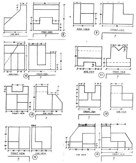
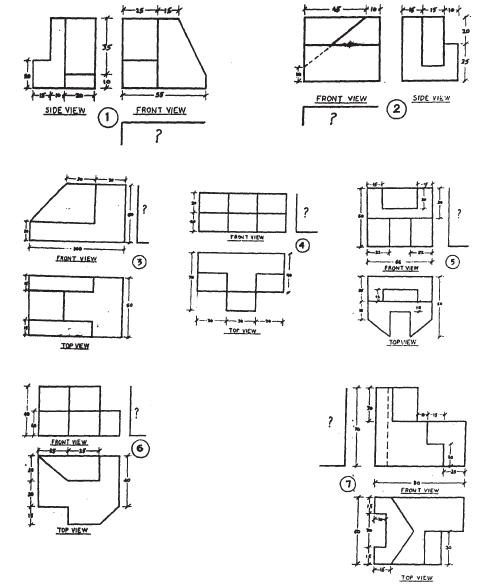
To perform the following jobs from the given views of the prescribed Machine Block
(Two).
1. Block-One, by the external examiner.
2. Block-Two, by the internal examiner.
Value-Points
Part 'A'
1. Copy the given views 1x2=2
2. Drawing the missing view with hidden lines 1½x2=3
3. Sketching the Isometric view vithout hidden edges 2½x2=5
4. To make the machine block of the above in three dimensions.
(not to scale but approximately proportionately) drawn with
any medium i.e. thermocol, soap-cake, plasticine, clay, wax, orchsis ( available with flowerists) etc. 5x2=10
Part 'B'
Viva-voce-questions based on the practicals 5
Performed in Part 'A'
Sessional Work:
Solutions of the fifteen prescribed Machine Blocks. 5
Total 30 Marks


Important:
(i) All dimensions are in mm.
(ii) The above diagrams are not to scale.
(iii) Assume suitably, missing or mismatching dimensions, if any.
(iv) Follow I angle method of projection only in all drawing or sketches.